rubyist

Making a Thing

I recently acquired a 3D printer. I am building a project where I want some custom enclosures and a custom display and I figured what the hell, may as well get a 3D printer and print them. Turns out, 3D printing is pretty awesome. This post isn’t about that project, though, that’ll come later. This post is about a thing I made that I needed. I’ve never really designed and made a real thing before so I thought I might document the process and share it. If you have experience doing this, this will be boring, elementary, and probably wrong.

The Thing

I collect and enjoy listening to records. I’m not an avid hipster or anything, all of my gear is 25+ years old, but it’s fun. A while ago I bought a used VPI record cleaner on ebay. It is a fantastic record cleaner. It’s expensive, but sometimes you can find a good deal on ebay and get it for considerably less money.

The cleaner I bought, however, did not come with the adapter that allows it to hold 7” 45 RPM records, so to date I have been unable to clean my 45s with it. VPI makes an adapter but it’s $30 and I’ve never felt like spending that kind of money for a simple piece of plastic. I once tried to make one from stuff at home depot, but I messed it up and never tried again. Tonight I figured I’d print one up.

Version 1

I broke out the calipers and made some simple measurements and threw a design together in OpenSCAD.

I sent it off to the printer and immediately realized I’d made a mistake.

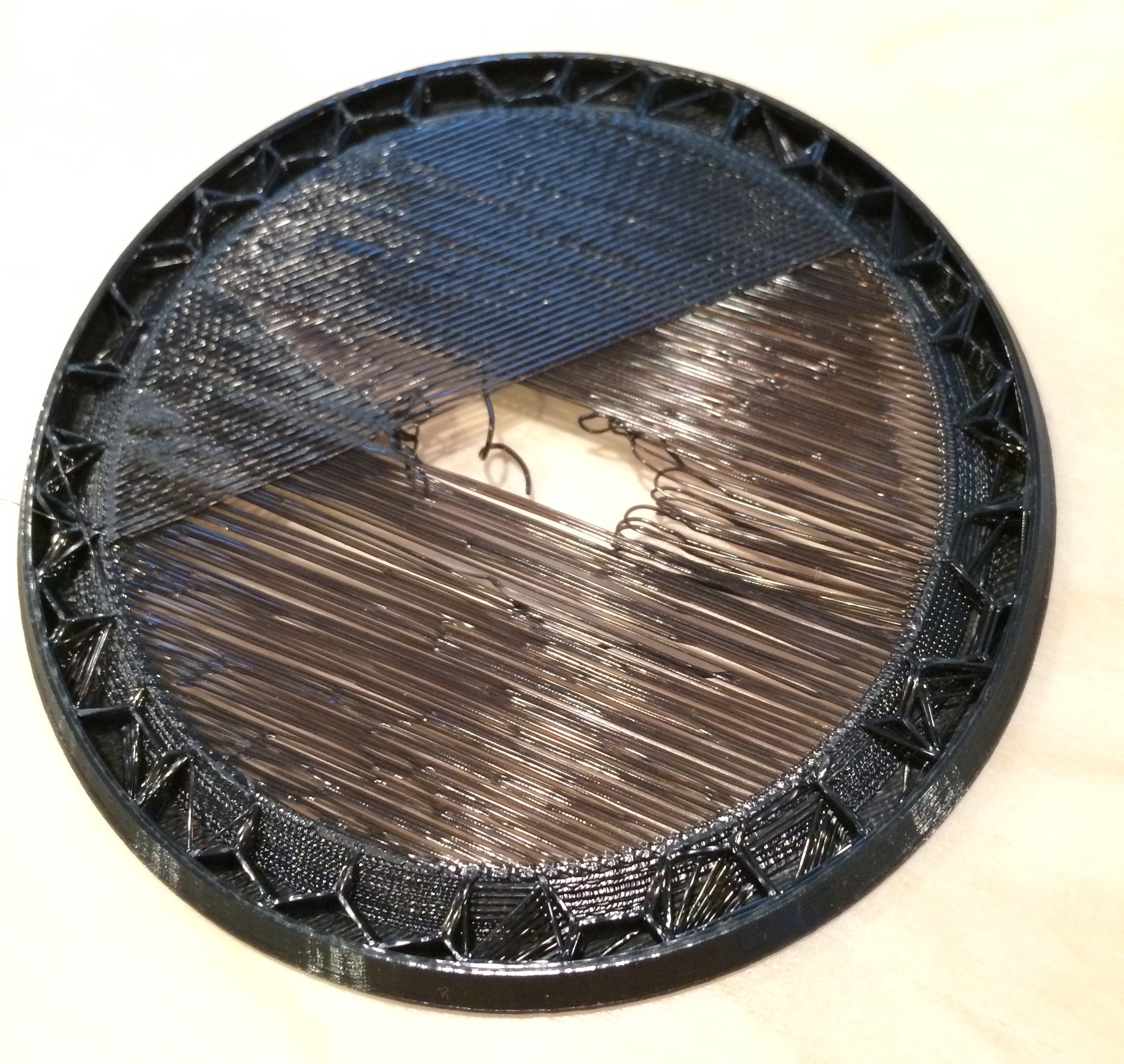
Rookie mistake. You can’t print across that much space without supports. Supports are extra structure that break away after you’re done. They help the printer make overhangs and span open space like that. So I cancelled the print, went back into the slicer, and had it add supports. This time the print finished, although it was a little rough on the underside, even though it used supports. I think Makerware is a little kooky with how it designed the supports.

I was pretty excited about this because it printed and except for some minor junk on the underside it looked pretty good. Then I tried to use it.

The problem here is that it’s too high. The post is threaded and there’s a little knurled screw piece that screws onto it to clamp everything down. The threaded post was not coming through the piece. I failed to measure and pay attention to the height of this screw. The hole was also not quite wide enough. The piece fit over the threaded portion of the screw, but not the unthreaded base, so the piece didn’t quite sit all the way down.

Version 2

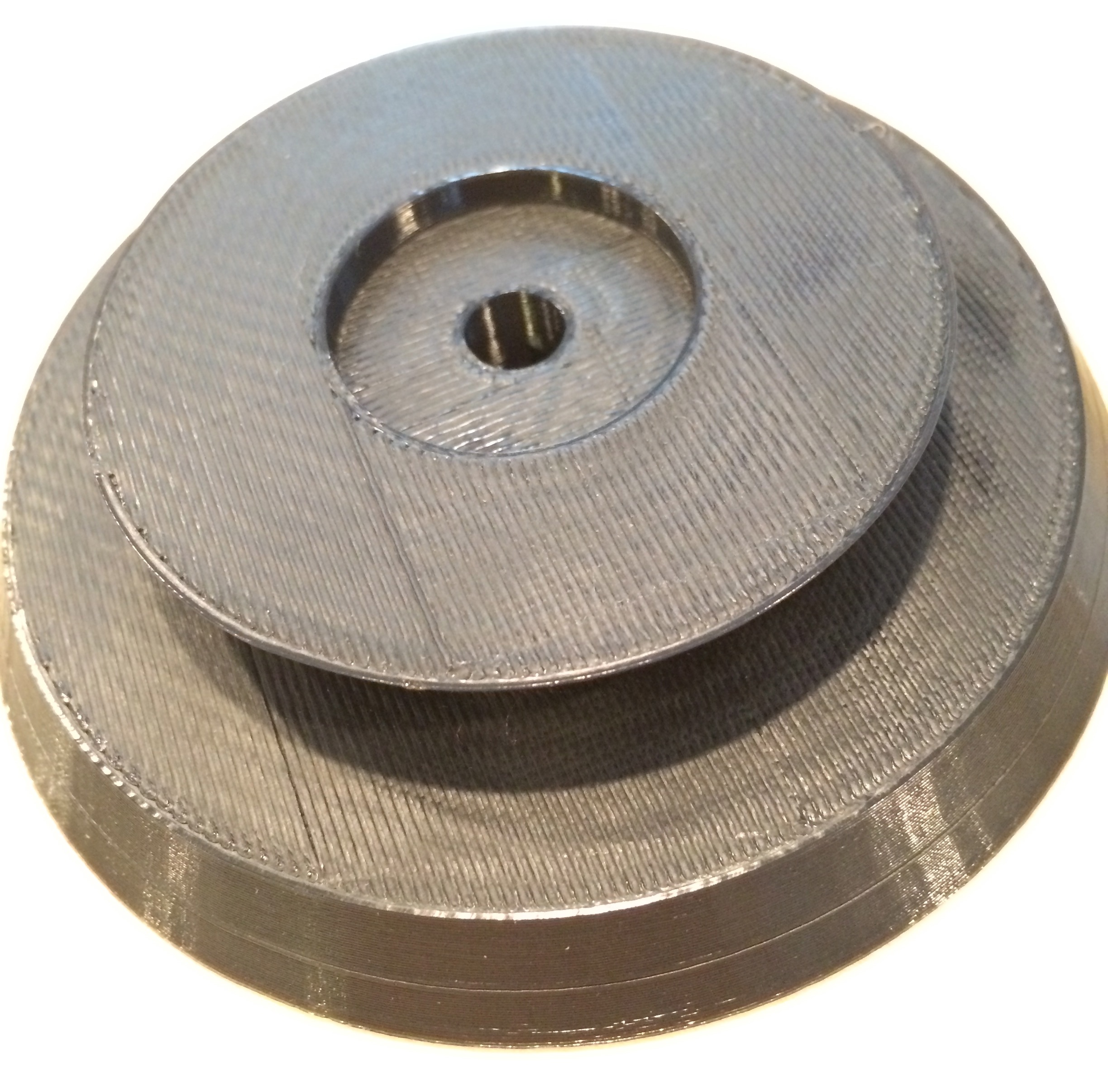
Back into OpenSCAD. I lopped off the top to bring the height down. I also flipped it so that the wider radius of the cylinder was at the top. This would make it easier to grab and pull off the cleaner. I also had this brilliant idea to add a little disk at the bottom the size of the hole in a 45 to help center it. Amazing!

Off to the printer it went. I was concerned it needed supports because of the large opening, so I selected the option in Makerware. It, however, did not feel the need to print any. The print turned out pretty fine, though a little rough on the underside because of the long stretches.

This time I had the height right, there was plenty of screw for the nut to grab onto. However, I neglected to make the center hole big enough, so it still didn’t quite sit all the way down.

I also realized that the clever retainer disk I had made wasn’t actually doing anything. In order to lock the record into place it would have to be below the surface of the main body. To get that to happen, I’d have to print the piece upside down, and if that were the case I don’t think that disk would have printed very well at all.

I thought about making the disk solid all the way up but decided to just simplify, simplify, simplify.
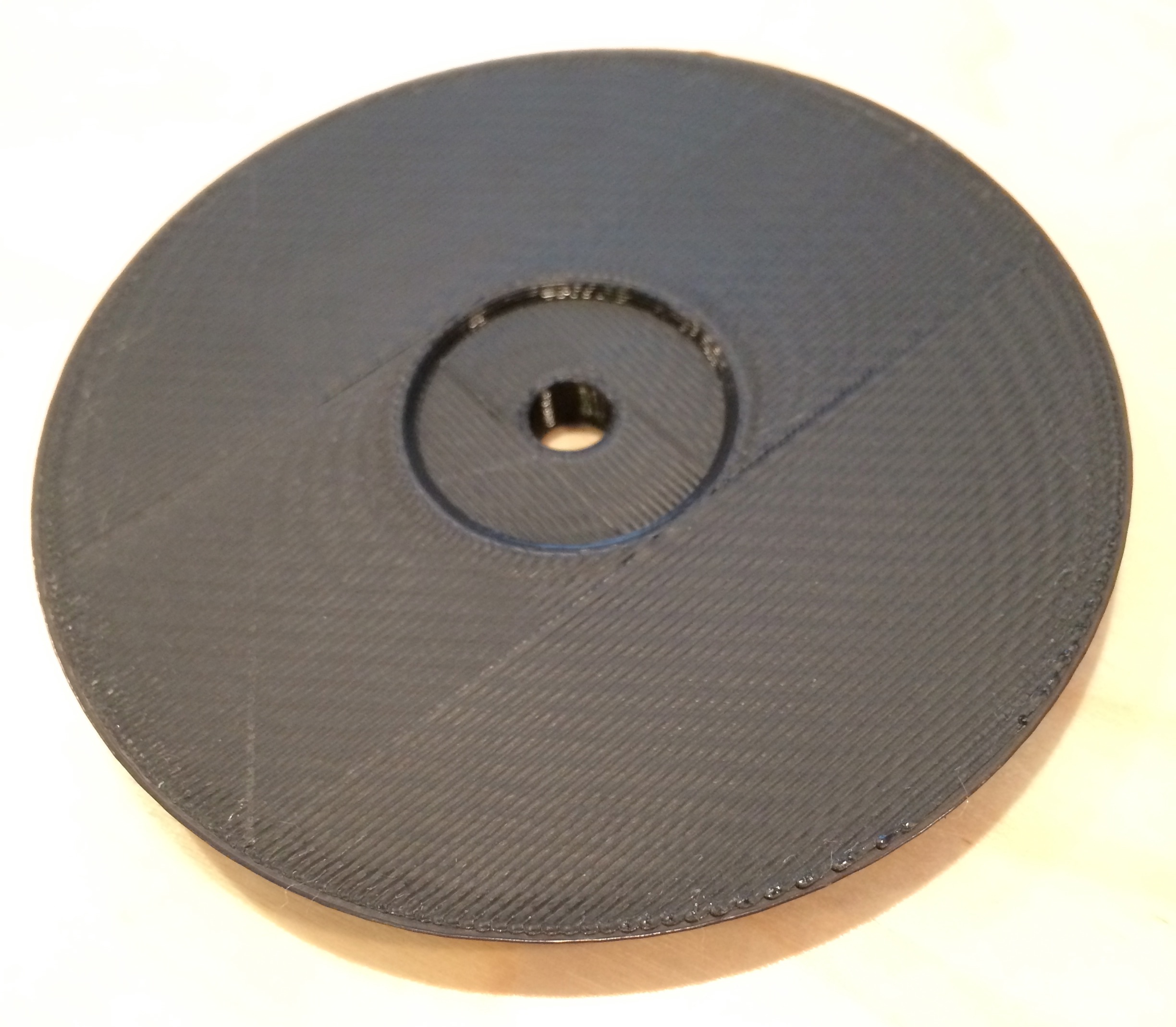
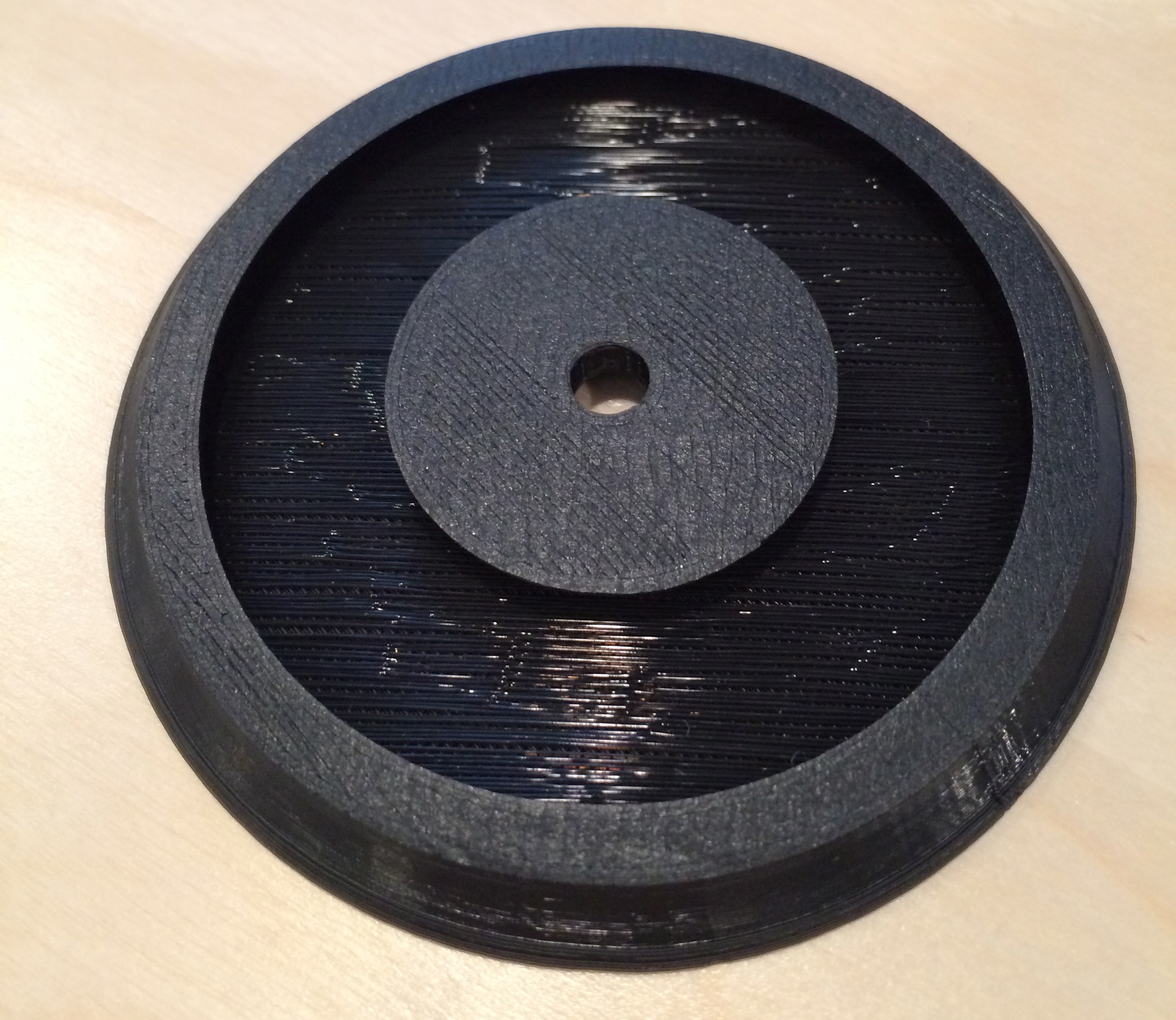
Version 3

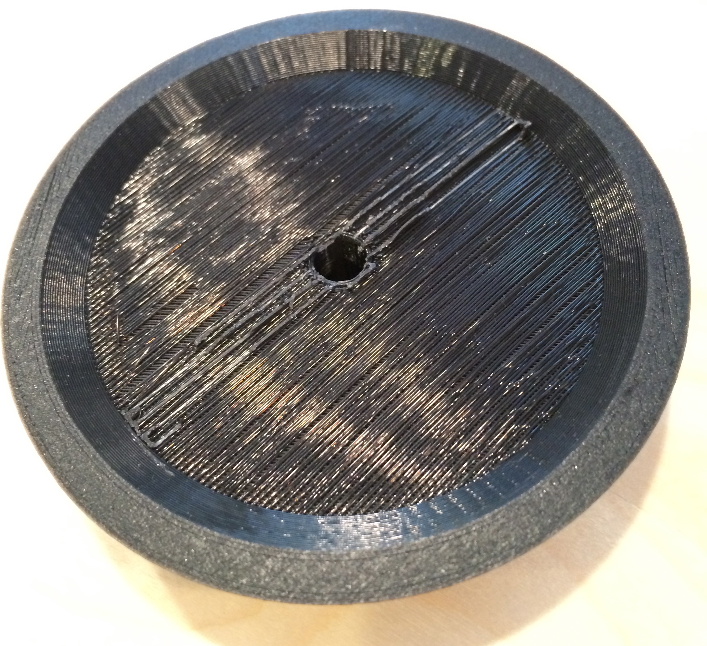
I went back into OpenSCAD and decided to just make the thing a solid piece, keeping the indent in the top for the screw to rest in.

That printed very well with no mess ups, because it’s a very simple piece.

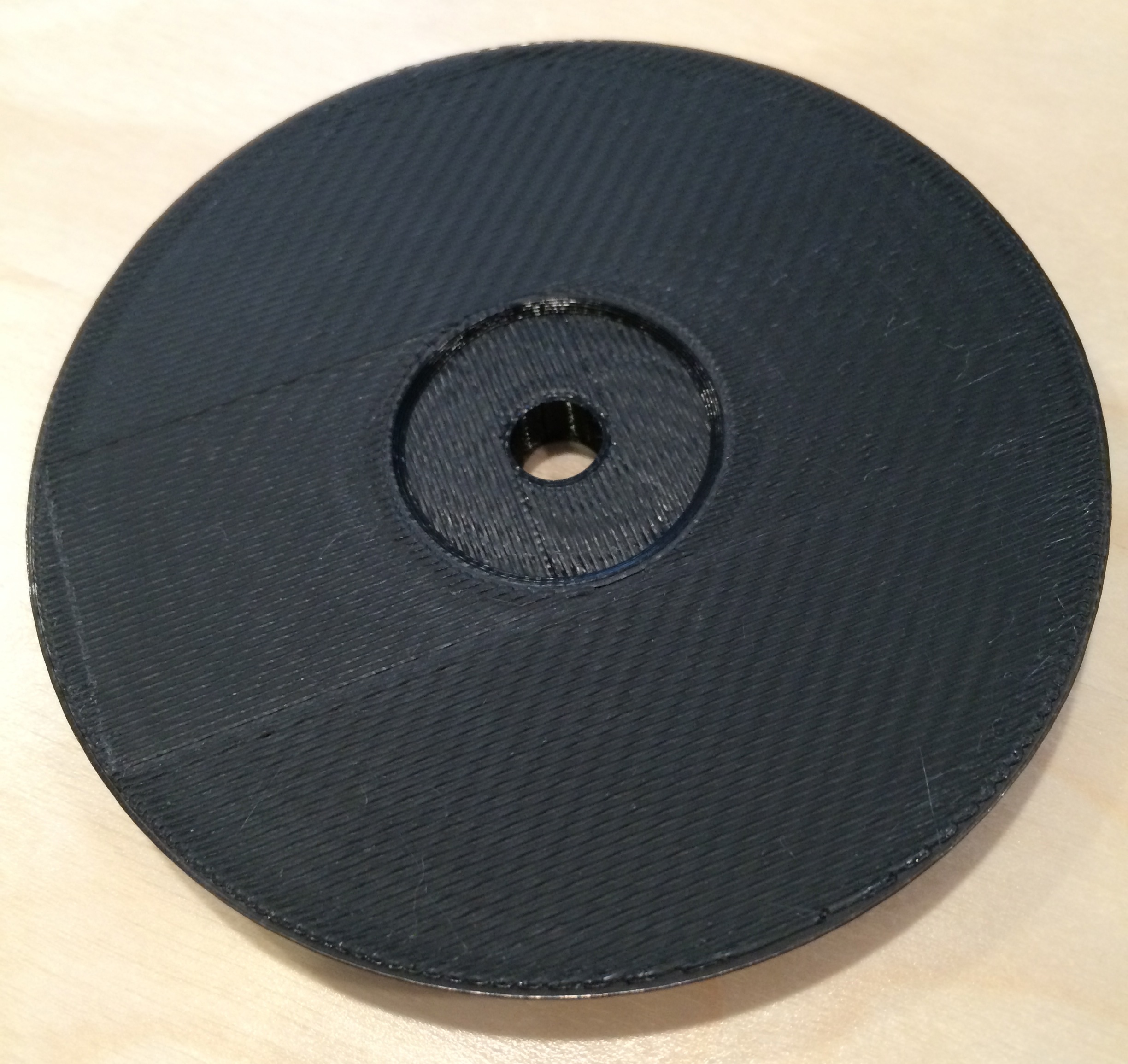
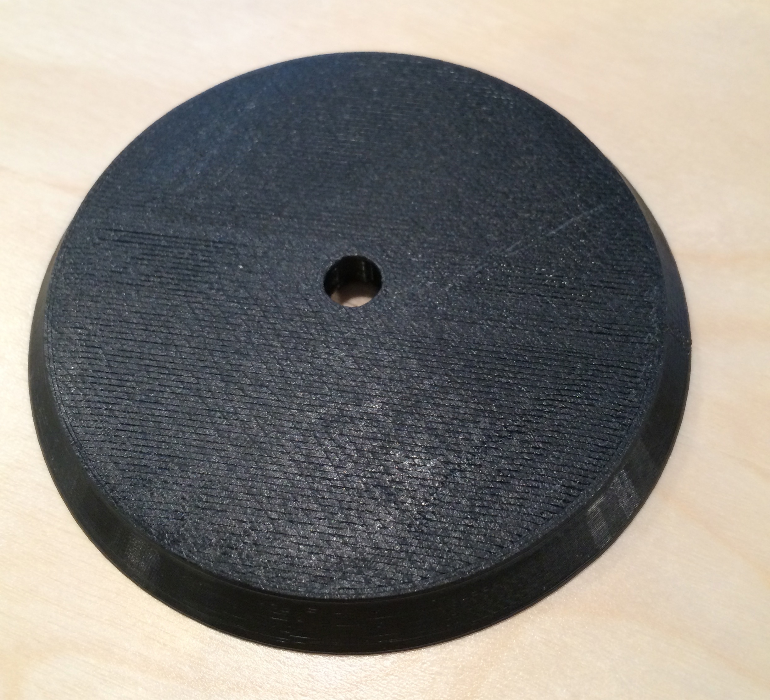
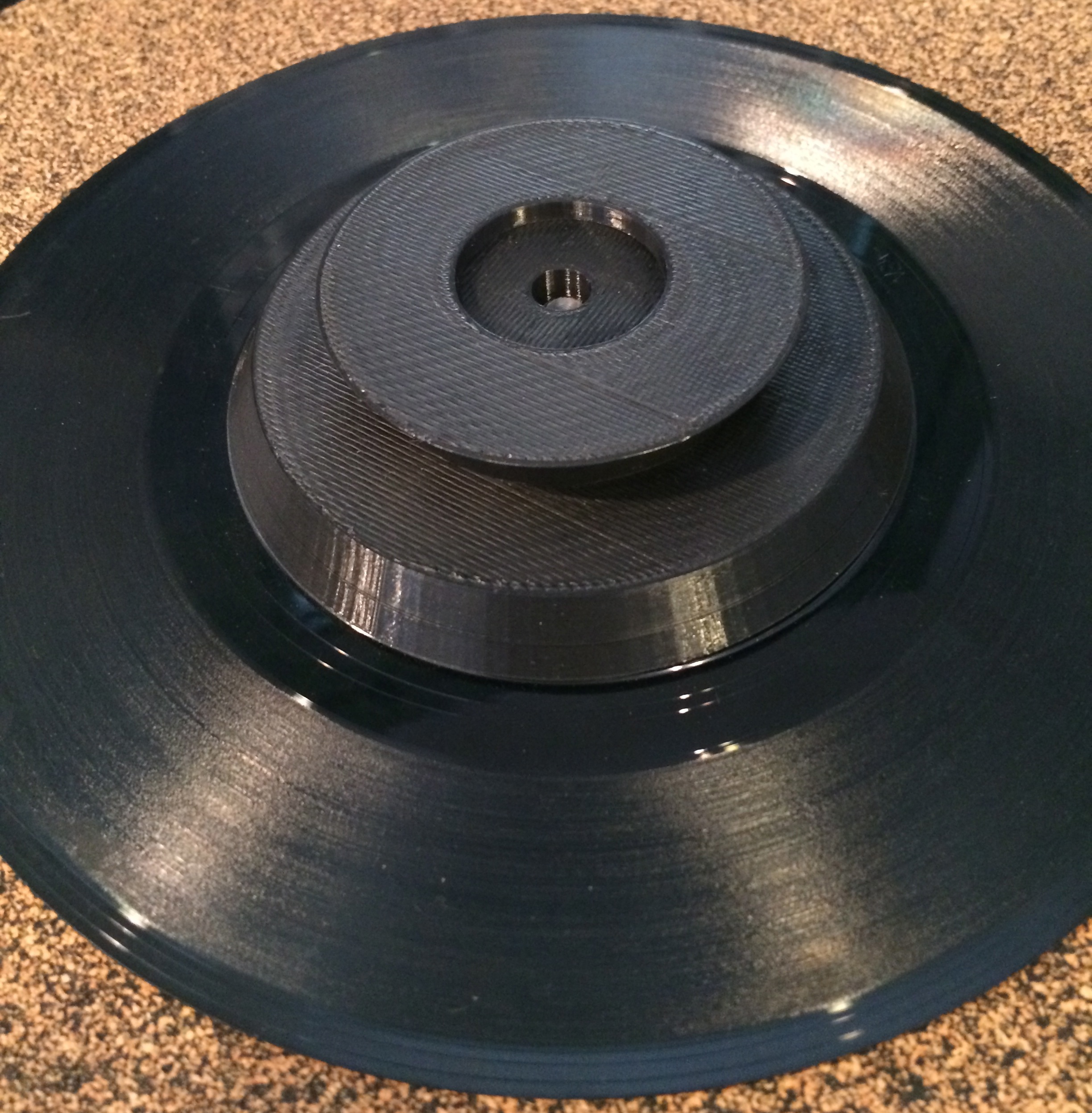
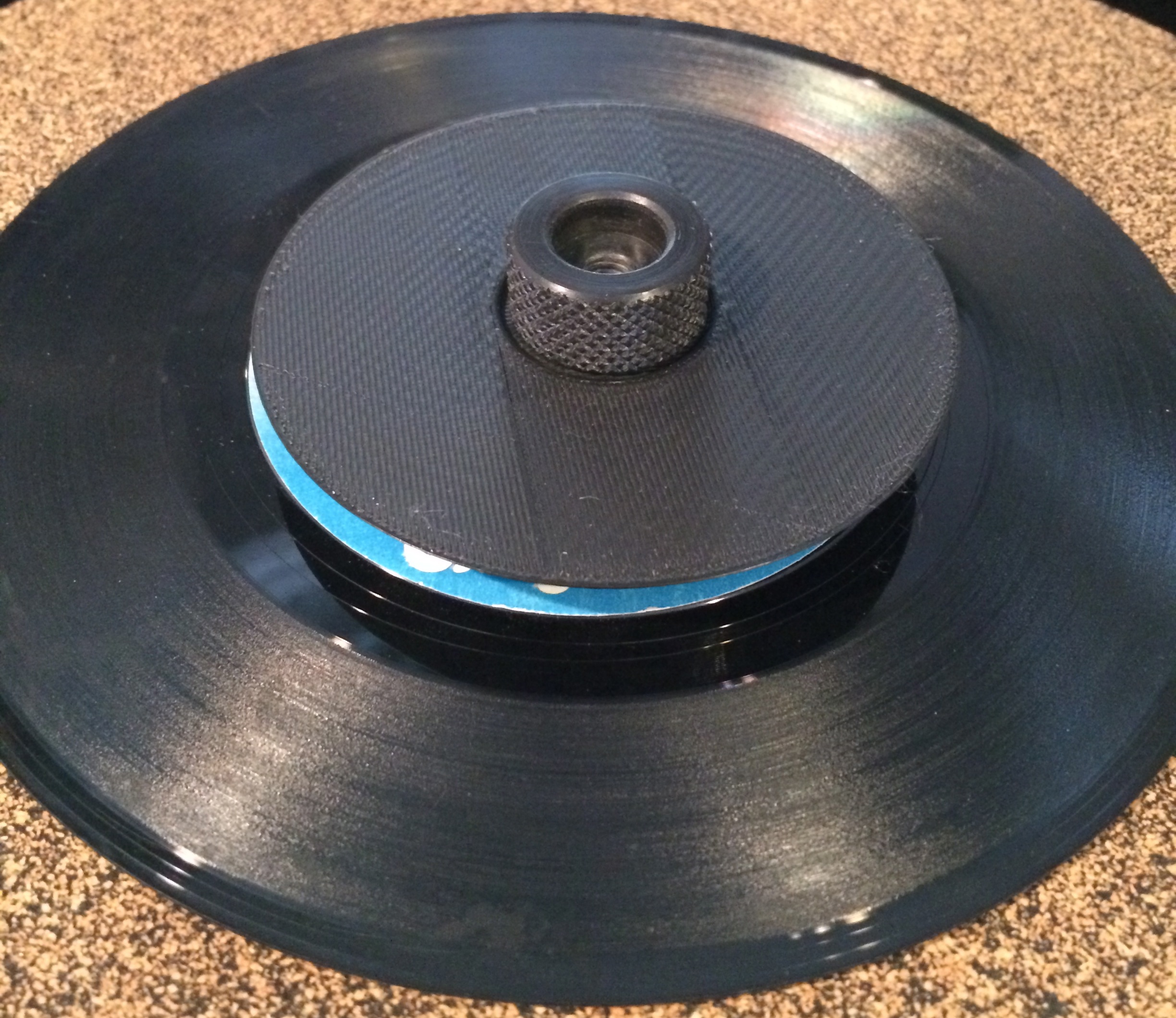
I also remembered to make the screw hole bigger, so now everything fit. The screw clamped it down nice and tight. I did make a mistake though, do you see it?

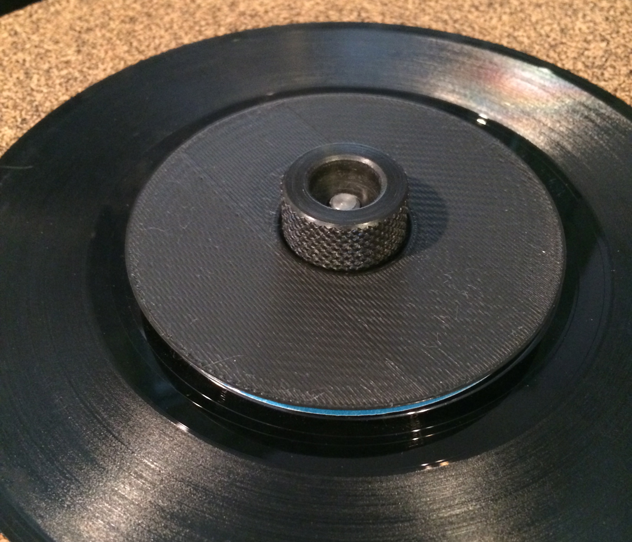
After lopping the top off and switching the radii I neglected to enlarge them so the bottom of the cylinder fully covered the record label. I fixed it up in the scad and STL files but decided to not print a new one. This is good enough for now and I’ve got other things to do.

Lessons Learned

I learned a good deal about designing things in this process. I learned technical things about printing like using supports, the effects of infill percentage, and how you orient pieces on the platform so they print well.

Most importantly, I think, I learned to keep the design of the thing simple. I am not a mechanical engineer or a product designer. I only barely know what I’m doing. I tried making it look pretty and fancy, but after trial and error arrived at what was essentially a cylinder of plastic with a hole in the middle. The two adornments it has (the bevelled edge and the indentation in the top) are completely functional. I will remember this while I’m designing more things.

If you happen to need this thing, you can grab it yourself from Thingiverse or from rubyist/3d on GitHub.

LED Strips as 7 Segment Display

In this post, I’ll detail the steps I took to use LED RGB Strips to back a large, wall-mounted seven segment display for rubyist/pingduino. Pingduino is an arduino based score keeper for ping pong games. A full build write-up will be posted here soon (after I finish building it). In the write-up I’ll detail the iterations on the display that lead to this point, but this post will focus only on my final implementation.

With these LED strips, each LED is individually addressable. You can turn a single LED on or off, or modify its color without affecting any other LEDs in the strip. They are also conveniently sliceable so you can cut the strip then solder wires between the pads to put some space between the LEDs. These strips require only one IO pin on the arduino and no other components. Contrast this to using a shift register based approach where you need one chip per digit, a resistor for each LED, and 3 pins on the arduino. Also, a lot of patience when routing the final PCB.

The display will be modelled after a typical 7-Segment LED display. I’ll use 3 LEDs for each segment, cutting and wiring the strips like so:

I didn’t want to cut up my strips until I’d tested the code, so I laid it out like this:

Ultimately I’ll need 4 digits to display the scores, but I started testing with one digit. First up, I drew out a table to figure out the state of each LED given the digit (0 – 9) I wanted to display. I broke the table up by 4 bits because I figured I’d be writing these out in hex in the code, this just makes figuring out the hex a bit easier. Given we have 7 segments with 3 LEDs per segment, we need 21 bits to store the states for any given digit, so the first 3 bits will always be 0. You’ll see in the code that these bits are ignored anyway.

For my first piece of test code I just iterated through the numbers and checked that the appropriate LEDs were lit.

1
2
3
4
5
6
7
8
9
10
11
12
13
14
15
16
17
18
19
20
21
22
23
24
25
26
27
28
29
30
31
32
33
34
35
36
37
38
39
40
41
42
43
44
#include <Adafruit_NeoPixel.h>

#define PIN 8

Adafruit_NeoPixel strip = Adafruit_NeoPixel(42, PIN, NEO_GRB + NEO_KHZ800);


unsigned long DigitBytes[] = {
 0x0003FFFF, // 0
 0x000001F8, // 1
 0x001C7E3F, // 2
 0x001C0FFF, // 3
 0x001F81F8, // 4
 0x001F8FC7, // 5
 0x001FFFC7, // 6
 0x000001FF, // 7
 0x001FFFFF, // 8
 0x001F81FF  // 9
};

void setup() {
  strip.begin();
}

void showDigit(int d) {
  unsigned long digit = DigitBytes[d];

  for (int i = 0; i < 21; i++) {
    if (digit & 1) {
      strip.setPixelColor(i, 0xFF0000);
    } else {
      strip.setPixelColor(i, 0x000000);
    }
    digit = digit >> 1;
  }
  strip.show();
}

void loop() {
  for (int x = 0; x < 10; x++) {
    showDigit(x);
    delay(5000);
  }
}

In this code, we set up an array with the hex values determined from the table above. unsigned long are 32 bits, so there’s an extra 8 bits in the hex values that you don’t see laid out in the table. To display a number we pull out the hex value then loop through each bit, which corresponds to an LED, and see if it needs to be turned on or off. We stop short of all 32 bits available so we don’t write over any LEDs farther down the line. This will be important when we add more digits to the display.

So, this test worked. Ping pong scores, however, use more than one digit. To display two digits we should be able to just add an offset to showDigit(), like so:

1
2
3
4
5
6
7
8
9
10
11
12
13
14
15
16
17
18
19
20
21
void showDigit(int d, int offset) {
  unsigned long digit = DigitBytes[d];

  for (int i = offset; i < offset + 21; i++) {
    if (digit & 1) {
      strip.setPixelColor(i, 0xFF0000);
    } else {
      strip.setPixelColor(i, 0x000000);
    }
    digit = digit >> 1;
  }
  strip.show();
}

void loop() {
  for (int x = 0; x < 10; x++) {
    showDigit(x, 0);
    showDigit(x, 21);
    delay(5000);
  }
}

This should light up the appropriate segments, and in fact it does. Ping pong has two players, each needing two digits. You can push all four digits down the line by continuing to scale the offset like this.

The score is kept as an integer in the code, so it’d be nice to just pass 10 to show the score of 10. This is easy enough:

1
2
3
4
5
6
7
void showScore(int score) {
  int ones = score % 10;
  int tens = score / 10;

  showDigit(ones, 21);
  showDigit(tens, 0);
}

This, in fact, works. Here’s the test strip lighting up the segments for the number 42. The digit 4 is segments b c f g, and the digit 2 is segments a b d e g.

Using this strategy you can then add more offets to be able to push out all the digits. For two players we need four digits total, so player 2’s tens offset would be 42 and the ones offset would be 63.

Note: Be careful hooking this many LEDs to your arduino. On USB power it’ll drive the 60 LEDs that are in the 1 meter strip without much problem, but it starts to flake out when adding more, depending on how many you’ve got lit up and the brightness. In the final build the strips will have their own power supply that can handle the current draw needed.

If you’d like to use this technique and use something other than 3 LEDs per segment it should be pretty easy to do. You can avoid hardcoding the offsets by doing something like this:

1
2
3
4
5
6
7
8
9
#define LEDSPERSEGMENT 3

void showScore(int score) {
  int ones = score % 10;
  int tens = score / 10;

  showDigit(ones, (LEDSPERSEGMENT * 7));
  showDigit(tens, 0);
}

Don’t forget to modify the for loop in showDigit in a similar way. You will, of course, have to generate an appropriate array of bitmaps to use. I’ll leave that up to you! In the next post I’ll design and build a case for this and show how the LED strips are sliced up and wired back together to make the digits.