In this post, I’ll detail the steps I took to use LED RGB Strips to back a large, wall-mounted seven segment display for rubyist/pingduino. Pingduino is an arduino based score keeper for ping pong games. A full build write-up will be posted here soon (after I finish building it). In the write-up I’ll detail the iterations on the display that lead to this point, but this post will focus only on my final implementation.
With these LED strips, each LED is individually addressable. You can turn a single LED on or off, or modify its color without affecting any other LEDs in the strip. They are also conveniently sliceable so you can cut the strip then solder wires between the pads to put some space between the LEDs. These strips require only one IO pin on the arduino and no other components. Contrast this to using a shift register based approach where you need one chip per digit, a resistor for each LED, and 3 pins on the arduino. Also, a lot of patience when routing the final PCB.
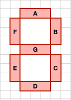
The display will be modelled after a typical 7-Segment LED display. I’ll use 3 LEDs for each segment, cutting and wiring the strips like so:
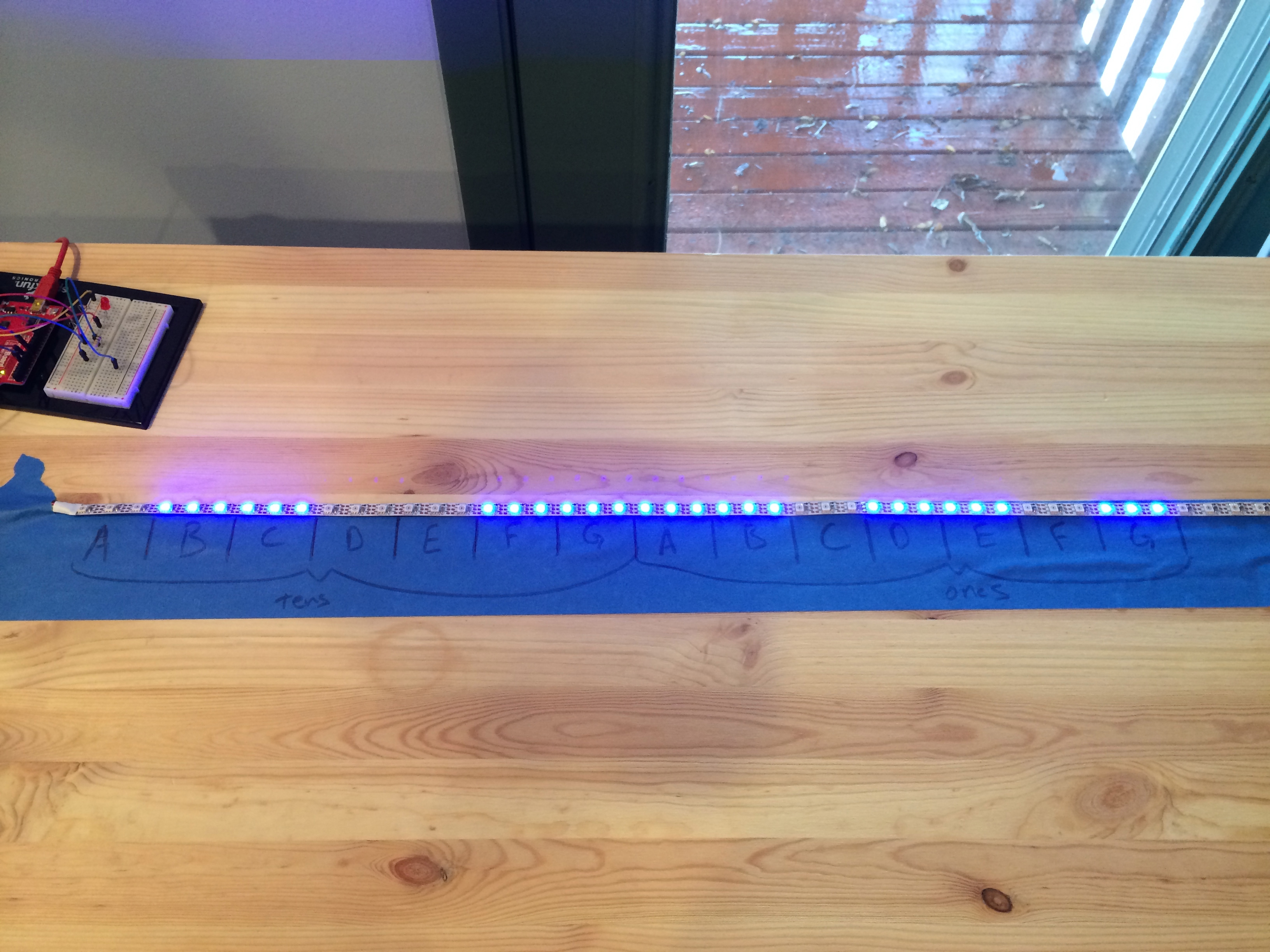
I didn’t want to cut up my strips until I’d tested the code, so I laid it out like this:

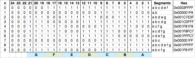
Ultimately I’ll need 4 digits to display the scores, but I started testing with one digit. First up, I drew out a table to figure out the state of each LED given the digit (0 – 9) I wanted to display. I broke the table up by 4 bits because I figured I’d be writing these out in hex in the code, this just makes figuring out the hex a bit easier. Given we have 7 segments with 3 LEDs per segment, we need 21 bits to store the states for any given digit, so the first 3 bits will always be 0. You’ll see in the code that these bits are ignored anyway.
For my first piece of test code I just iterated through the numbers and checked that the appropriate LEDs were lit.
1 2 3 4 5 6 7 8 9 10 11 12 13 14 15 16 17 18 19 20 21 22 23 24 25 26 27 28 29 30 31 32 33 34 35 36 37 38 39 40 41 42 43 44 | |
In this code, we set up an array with the hex values determined from the table above. unsigned long are 32 bits, so there’s an extra 8 bits in the hex values that you don’t see laid out in the table. To display a number we pull out the hex value then loop through each bit, which corresponds to an LED, and see if it needs to be turned on or off. We stop short of all 32 bits available so we don’t write over any LEDs farther down the line. This will be important when we add more digits to the display.
So, this test worked. Ping pong scores, however, use more than one digit. To display two digits we should be able to just add an offset to showDigit(), like so:
1 2 3 4 5 6 7 8 9 10 11 12 13 14 15 16 17 18 19 20 21 | |
This should light up the appropriate segments, and in fact it does. Ping pong has two players, each needing two digits. You can push all four digits down the line by continuing to scale the offset like this.
The score is kept as an integer in the code, so it’d be nice to just pass 10 to show the score of 10. This is easy enough:
1 2 3 4 5 6 7 | |
This, in fact, works. Here’s the test strip lighting up the segments for the number 42. The digit 4 is segments b c f g, and the digit 2 is segments a b d e g.
Using this strategy you can then add more offets to be able to push out all the digits. For two players we need four digits total, so player 2’s tens offset would be 42 and the ones offset would be 63.
Note: Be careful hooking this many LEDs to your arduino. On USB power it’ll drive the 60 LEDs that are in the 1 meter strip without much problem, but it starts to flake out when adding more, depending on how many you’ve got lit up and the brightness. In the final build the strips will have their own power supply that can handle the current draw needed.
If you’d like to use this technique and use something other than 3 LEDs per segment it should be pretty easy to do. You can avoid hardcoding the offsets by doing something like this:
1 2 3 4 5 6 7 8 9 | |
Don’t forget to modify the for loop in showDigit in a similar way. You will, of course, have to generate an appropriate array of bitmaps to use. I’ll leave that up to you! In the next post I’ll design and build a case for this and show how the LED strips are sliced up and wired back together to make the digits.